Most of my computers have been sitting in a noise-insulated 19“ rack for 6 years or so. Although I’ve been administrating real servers for more than a decade, I still get a kick out of cosplaying as sysadmin with machines that I can actually touch, rather than being located in some rented data hundreds of kilometers away.
The rack I bought came with a temperature-controlled fan that pulled air through the whole box (just tall enough to fit under a desk), but could only run at 0% and 100% speed, because the temperature control was just a binary switch. That kinda defeated the point of the rack being noise-insulated, because even Noctua fans make some noise at 100% speed.
At the time, I started getting into electronics, so naturally I wanted to build my own that does things exactly as I need them.
Rack Control v1🔗
This article is actually about v1, but let’s put things into context. Version 1 is based on ESP32, and sports these features:
- Temperature (and other sensors) measured via BMP280.
- PWM-controlled Noctua fans, controlled in tandem.
- Speed reading of one of the fans.
- Linear temperature-based auto-control of fan speed.
- Metrics reporting via custom-schema MQTT messages.
- PWM override via MQTT.
Although I wanted to build a PCB for it, it never left the bread board. Today, it looks like this:
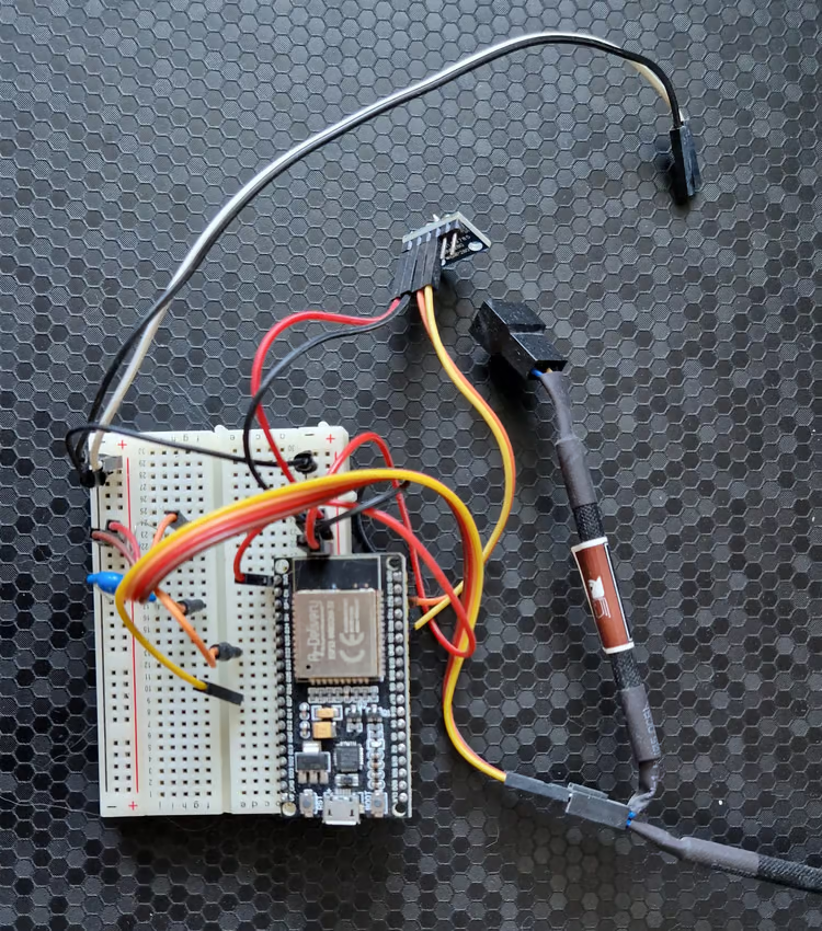
The black and white wires were connected to the 12V power supply that came with the original cooling solution to power the fans, whereas the board was powered via USB (conveniently connected to a machine I can use to reprogram on the fly).
The capacitor and resistor were necessary for fan speed reading, but I picked the wrong capacitor size, so I only got very noisy readings.
The fans were controlled via splitter to connect both to 12V, GND, and PWM, but only one fan was connected to the RPM pin.
The good🔗
Credit where credit’s due - it ran continuously for almost 6 years without requiring any repairs, and kept my electronics safe.
The code was very minimal and had few things that could go wrong, improving reliablity.
The bad🔗
Back then, I hadn’t gotten into Home Assistant yet, so my MQTT messages didn’t integrate natively via MQTT. I used NodeRED to control the thing and view metrics at the time, and later changed it so it would transform the MQTT messages to be Home Assistant friendly, but it still wasn’t a native integration.
It was also kinda annoying that it would stop communicating with MQTT after months of continuous operation, but I rarely looked at the metrics and it kept cooling well, so I never bothered trying to figure out the cause until I had already built the replacement. Take a look at the following piece of code for reconnecting after a lost network connection:
void reconnectNetwork() {
    if (WiFi.status() == WL_CONNECTED) {
        return;
    }

    Serial.print("Connecting to network");
    while (WiFi.status() != WL_CONNECTED) {
        delay(1000);
        Serial.print(".");
    }
    Serial.println("!");
    Serial.println(WiFi.localIP());
}
Although logging claims that it’s connecting, there is no WiFi.begin, so it just waits for something to happen that will never happen. Really embarrassing.
The problem that drove me to finally build v2 was cooling power: At full load, the two Noctua fans wouldn’t be enough to keep at reasonable temperatures, and the rack contents could go all the way past 60°C, reducing the lifetime of electronic components.
Essentially, this meant I’d have to crack the door to let more air in whenever I want to play some games. Given that I prefer to stream games from the couch, I’d have to walk all the way over to my office to crack the door, which I sometimes forgot about, only to remember when the frame rate started dropping due to overheating.
Requirements for version 2🔗
Expanding upon the features of v1, this is what I wanted from v2:
- Sufficient cooling power to run at full load with the rack door shut.
- Focus on reliability, so cooling would err in favor of caution, using measures such as:
- Run fans at full speed if sensors fail.
- Auto-reset via watchdog to prevent lockup.
- Use of defensive control structures.
- Native Home Assistant integration via MQTT.
- Control each fan individually to implement interesting cooling algorithms.
- Measure each fan speed individually, because
it’s coolit allows us to monitor fans and detect failures.
Hardware design🔗
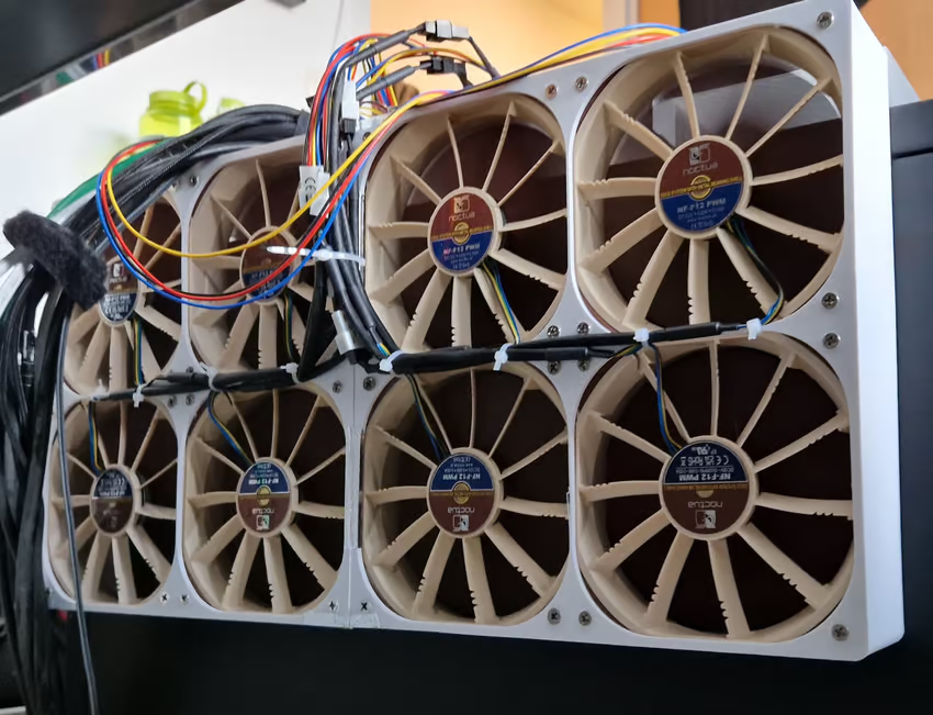
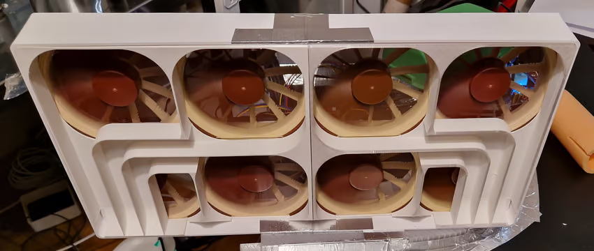
I figured more fans would be better, so my design uses 8 fans to pull air through the rack through a single-fan-sized opening on top.
The frame is printed out of PETG to be more temperature-resistant than PLA. PETG only starts warping at temperatures that must never happen inside of the rack, so it should be good enough.
The frame is also built to be easily detachable, as I suspected that I might need to revise parts of my design. That was the wisest decision in this project.
There isn’t enough space on top of the rack to pull the air out directly (still needs to fit under a table), so I also designed an elaborate air duct with temperature probe:
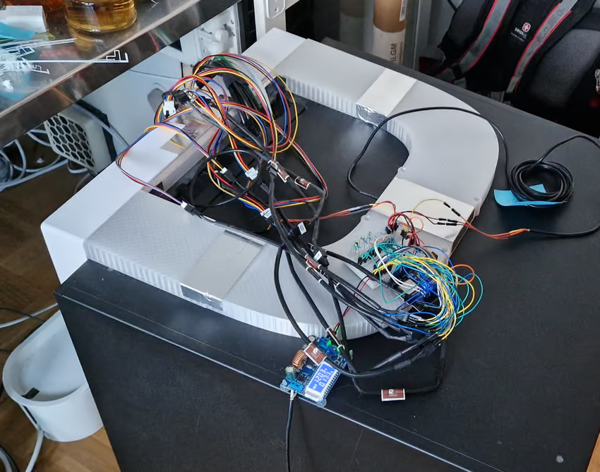
The air egress opening is in the middle of the rack’s top plate, and the duct splits up to offer air two ways towards the fans. When I was done, I taped everything with aluminium tape so air flow has no way to escape (and there are no shortcuts for surrounding air).
This is where I went colossally wrong🔗
I don’t know shit about aerodynamics, but suspected that using 8 fans to pull air through a hole the size of 1 fan could mean trouble. So I did what people who don’t know stuff do these days - talk to an LLM.
Although I tried prompting the LLM to be critical and inquisitive, I got the usual “you’re so smart - that will totally work”.
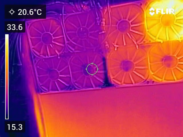
The reality was that cooling was barely better than with the old 2 fan solution, because the fans sucked in air through neighboring fans. Only the fans closest to the duct actually expelled hot air, while the others circulated room temperature air from outside.
This shows up pretty clearly in thermal imaging:
Attempted fix: Add air guides🔗
By holding my hands close to the non-performing fans, I could tell that air is being sucked in, although it should only be expelled. Therefore, the first attempted fix was to introduce air guides to make sure each fan gets a piece of the action, without having a shortcut to its neighbors. It looked gloriously symmetric:
…but temperatures didn’t improve a single bit. There were still plenty of gaps offering air an easier route. Thermal imaging confirmed that the extra bends aren’t doing air transport a favor:
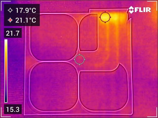
I could have used more tape in an attempt to close the gaps, but that wouldn’t have dealt with the additional drag that the fans have to fight because of the extra bends.
Attempted fix: Add more holes🔗
This sounds really stupid, but sometimes the stupid (and simple) solutions are best: The rack has a couple of places in the back where the metal is perforated to make it easier to add new cable openings. One such opening conveniently sat right beneath where the fan assembly is located. If I can’t get the air to go the complicated way through an existing hole, I just need a bigger hole closer by.
So basically, I cut a new hole into the rack, about the same area as 1.5 fans, and ran synthetic load again. Now, all fans transport hot air:
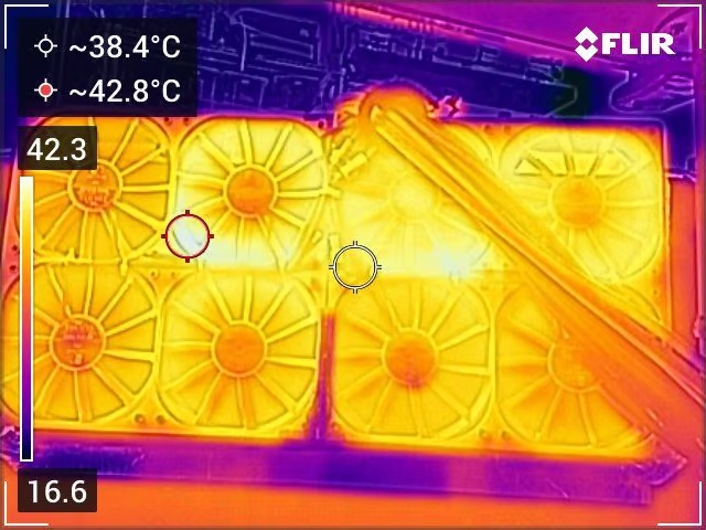
I don’t have a picture of the new hole, but the thermal image hints at its location - it’s behind the hottest area.
The best part is that the cooling system can now maintain a comfortable 41°C at full load when the rack door is closed!
Performance comparison🔗
To emphasize how much things improved, let’s see how temperature changed over time with the initial design:
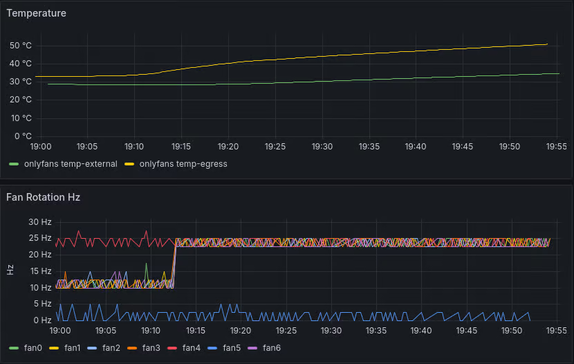
I aborted the test after an hour due to high temperatures. And don’t mind fan5’s weird speed readings - there was a short on the breadboard.
For comparison, the final iteration:
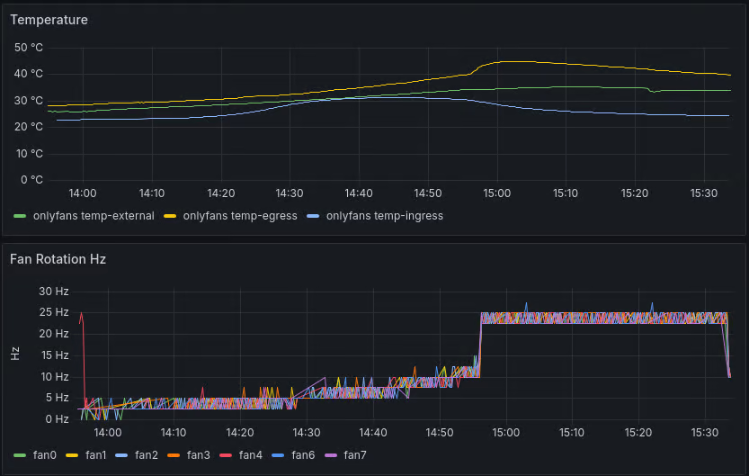
The temperatures even started dropping an hour in while the synthetic load was still ongoing, because full speed cooling was so effective!
The software side🔗
This part is less interesting than the hardware side, so I might elaborate in the future.
The short version: I went with a PID controller at first, but it was hard to teach it to prioritize silence below a certain temperature. In the end, I used a similar solution to v1 with a temperature-based linear increase in fan speed that is capped to maximum silent speed while the temperature is below a certain threshold.
The Home Assistant integration turned out quite rich, and I can monitor fans for problems based on discrepancy between expected and measured speed.
Will I make a PCB this time?🔗
I might just stick to the breadboard this time too, because it just works, but I’m curious about learning PCB design with KiCAD, so I might give that a try.
Conclusion🔗
Although I failed hard at first, I was ultimately able to meet all requirements by being pragmatic and going with a simple, stupid solution that works, rather than something extremely elaborate. It was still fun trying the elaborate way, and I had an opportunity to produce professionally-looking 3D designs that also printed very well.